Control systems:
A control system manages or regulates the behavior of systems using control loops.
There are two common classes of control action: open loop and closed loop.
In an open-loop control system, the control action from the controller is independent of the process variable.
An example of this is a central heating boiler controlled only by a timer. The control action is the switching on or off of the boiler. The process variable is the building temperature. This controller operates the heating system for a constant time regardless of the temperature of the building.
In a closed-loop/Feedback control system, the control action from the controller is dependent on the desired process variable.
Looking at the heating boiler example again, in this case, we would utilize a sensor/thermostat to monitor the building temperature and feedback a signal to ensure the controller maintains the building temperature close to the desired temperature set on the thermostat.
Robot Control System (PID):
Our line following robot will use a closed-loop/feedback control mechanism & will rely mainly on the 5 channel IR proximity line sensor module (Chapter 11).
The array of 5 IR sensors on the sensor module is set up so that when the robot is perfectly centered to the black line, only the center IR sensor pair will produce a LOW signal.
Suppose the robot approached a turning/curve or simply just not centered along the path. The black line will trigger 1 or 2 sensors simultaneously at some point. Producing either a non-center signal or 2 LOW signals adjacent to each other.
The possible combination of the sensor's output when the robot is going along the path would be as follow:
| Sensor 1 |
Sensor 2 |
Sensor 3 |
Sensor 4 |
Sensor 5 |
| 1 |
1 |
1 |
1 |
0 |
| 1 |
1 |
1 |
0 |
0 |
| 1 |
1 |
1 |
0 |
1 |
| 1 |
1 |
0 |
0 |
1 |
| 1 |
1 |
0 |
1 |
1 |
| 1 |
0 |
0 |
1 |
1 |
| 1 |
0 |
1 |
1 |
1 |
| 0 |
0 |
1 |
1 |
1 |
| 0 |
1 |
1 |
1 |
1 |
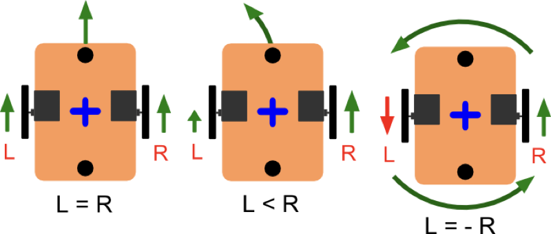
The PID algorithm in the controller aims to restore the robot's direction over the black line in an optimum way, with minimal delay or overshoot, through controlling the speed output of our robot's stepper motors.
Let's have a quick recap on the Proportional Integral Derivative Control (PID control) concept. (Image from Wiki: PID Controller)
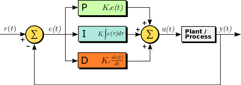
A PID controller (Line following robot controller) continuously calculates an error value e(t) as the difference between a desired setpoint r(t) and a measured process variable y(t), error value e(t)=r(t)-y(t).
Now let's add in an "Error Variable" derived from the 5 channel IR sensor reading above.
If the error variable is greater than 0, it means the path is on one side of the robot. And if the error variable is less than 0, it means the path is on the other side. Ideally, if the robot traveled along the straight line, the error variable will always remain as 0.
| Sensor 1 |
Sensor 2 |
Sensor 3 |
Sensor 4 |
Sensor 5 |
|
Error |
| 1 |
1 |
1 |
1 |
0 |
-> |
4 |
| 1 |
1 |
1 |
0 |
0 |
-> |
3 |
| 1 |
1 |
1 |
0 |
1 |
-> |
2 |
| 1 |
1 |
0 |
0 |
1 |
-> |
1 |
| 1 |
1 |
0 |
1 |
1 |
->
|
0 |
| 1 |
0 |
0 |
1 |
1 |
-> |
-1 |
| 1 |
0 |
1 |
1 |
1 |
-> |
-2 |
| 0 |
0 |
1 |
1 |
1 |
-> |
-3 |
| 0 |
1 |
1 |
1 |
1 |
-> |
-4 |
In the above setup (Table with the Error), The error e(t) is the difference between the current position of the robot y(t) and the desired position of the robot r(t).
Refer to the source code implementation below as:
void readSensorValues();
Finally u(t), in the above diagram is the output from the PID controller algorithm to control the speed of the motor:
void motorControl();
Proportional Term (P):
This term is proportional to the error. It is responsible for the magnitude of change required in the physical quantity to achieve the setpoint (e(t) = 0, robot aligned properly on the line).
The error e(t) gets multiplied with Kp and forms the proportional output of the controller.
Giving a higher Kp will increase the responsiveness of the line following robot. But if Kp is too high, it would lead to overshoots, and the robot might travel away from the path completely :)
Integral Term (I):
This term is the cumulative sum of all the previous error values. It affects the quickness of response of the system to the change from the set point.
The Integral term works to eliminate the steady-state error - the residual e(t) error after applying proportional control.
Small e(t) x Ki will cause the integral component to increase slowly. As a result, the integral output will continually increase unless the error is zero.
Differential or Derivative Term (D):
This term is the best estimate of the future trend of the error e(t) based on its current rate of change.
It works by reducing the effect of the error e(t). This slow down the rate of change of the physical quantity when it comes close to the setpoint sometimes known as the damping effect.
Increasing the Kd parameter will cause the Line Following Robot to react more strongly to changes in the error term and increase the overall control system response speed.
Final Equation:
PIDvalue = (Kp*P) + (Ki*I) + (Kd*D)
Source code implementation:
void calculatePID();
Where:
Kp is the constant used to vary the magnitude of the change required to achieve the setpoint (Robot aligned properly on the line).
Ki is the constant used to vary the rate at which the change should be brought in the physical quantity to achieve the set point.
Kd is the constant used to vary the stability of the system. Increasing derivative term decreases overshoot and yields higher gain with stability.
Calibration:
To keep it simple, we are going to opt with Trial & Error method. In this method, the Ki and Kd terms are set to zero first and the proportional gain Kp is increased until the Line Follower Robot starts to oscillate/wobble.
(Advance) Once you are happy with the response speed after tweaking Kp, slowly increase the value of Ki to reduce the oscillation/wobbling.
(Advance) After Kp & Ki has been set, Increasing derivative term Kd decreases overshoot and yields higher gain with stability. The robot will return quicker to the center line.
(Pro) Calibration might be a really painful if you need to compile & load the code every time.
Try to think along the line where you could use the Buttons (EndStop switch to increase those constant) or Serial Monitor to send the new constants down the line.
Once we reach Module B, you will learn how you can communicate with the Robot over WIFI. " Wireless baby...."
(Pro) Just for your own reading: Apart from Trial & Error method, another well known technique (method) used in calibration of PID control system is the Ziegler Nichols Method.
Read up more about it: Ziegler Nichols Method Wiki
Write up by MicroStar Labs
Todo:
- Create a path on a piece of paper (If you haven't done so)
- Implement the robot algorithm as an Arduino® sketch for the C3 CoreModule.
- Test it on your imaginary factory floor path