The Idea of modular hardware:
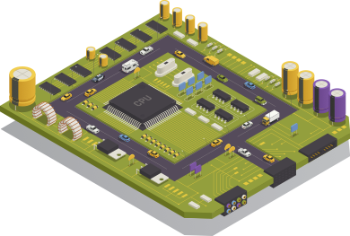
Modular hardware is a concept where a complex circuit is separated into separate modules instead of one complete setup.
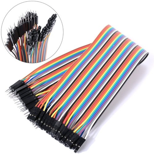
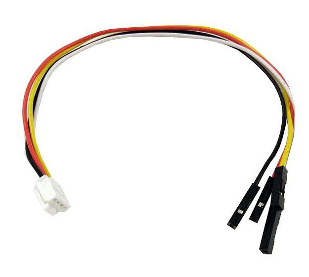
In electronics design, it means splitting a complete circuit into multiple smaller PCBs. The PCBs are then connected via cables or connectors.
The concept isn’t new & if you look at how computers are assembled, be it a desktop or your laptop. A single motherboard with slots for graphics cards, sound cards, and other peripherals is what modular hardware is all about.
Reason for modularity:
- Allow reuse, test & upgrade of individual components.
(microcontroller are upgraded every 2-3 years)
- Space Constrained.
- Task-specific customization.


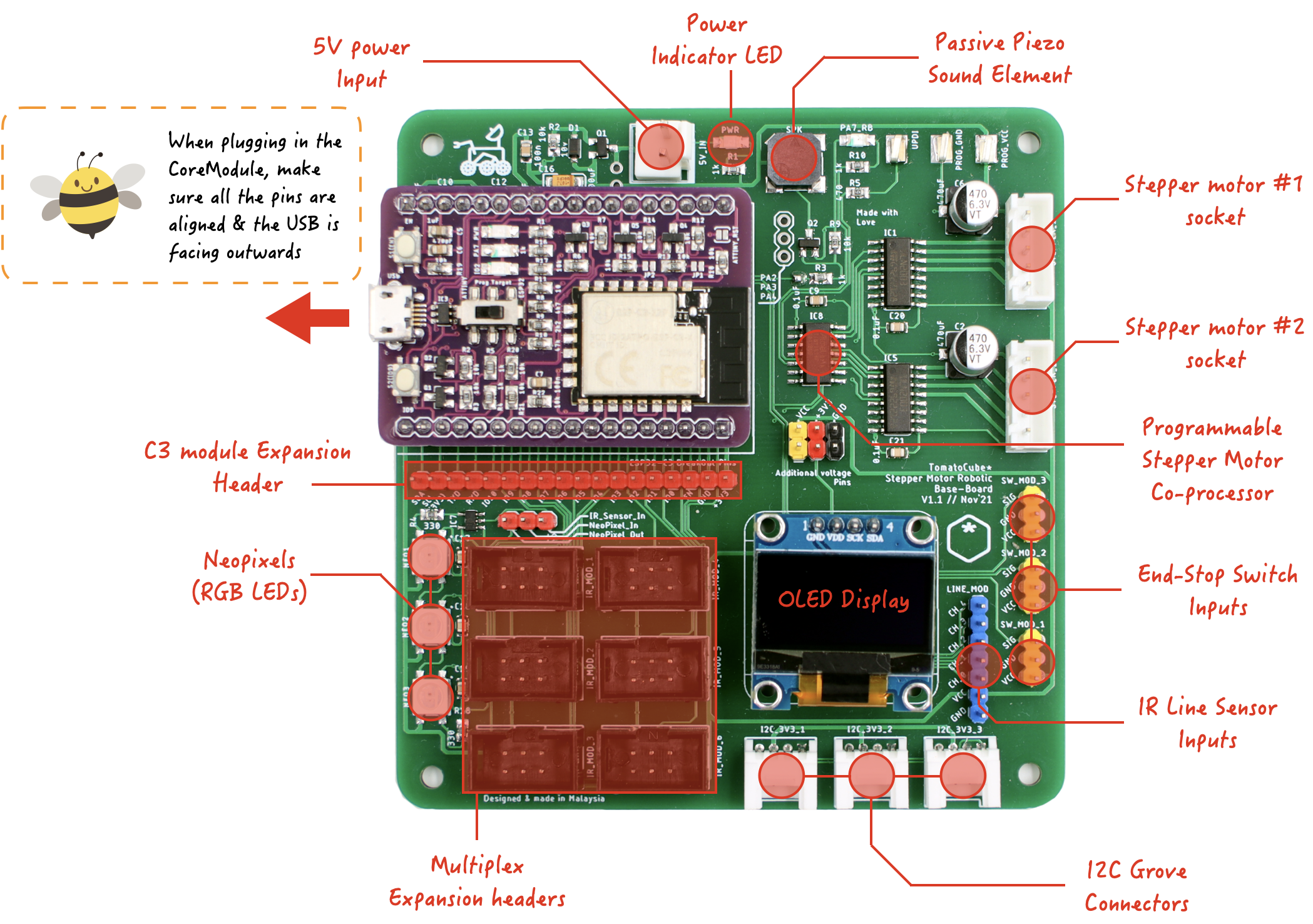
Parts of the Robotic Main Board:
Once the C3 CoreModule is matched up with the Robotic Mainboard, it immediately opens up a world of possibilities.
Here are some of the IO peripheral & modules as well as breakout that is presented on the Robotic MainBoard.
- 1x Sockets for Core module
- 1x Stepper motor co-processor & 2x JST connectors.
- 3x programmable RGB Chain-able Neo-pixels LEDs onboard.
- 1x i2C Graphical OLED display.
- 1x i2C port expanders for various sensors.
- - 3x EndStop (Microswitch) module connection.
- - 1x 5-Channel IR line module connection.
- 3x 3v3 i2C grove connectors for misc sensors/peripherals expansion.
- 1x (unpopulated) 5v i2c grove connectors.
- 6x Shrouded 3x2 pin header for IR modules (or others) expansion.
- 1x Passive Piezo sound element.
- 2x CoreModule Pin header breakout.
- 1x Additional Power Pin header breakout.
The image above shows the location of where the aforementioned breakout pins. Alternatively, you can also observe the printing on the board's silkscreen layer. Again, the printing on the silkscreen layer will give a hint at the purpose of those connections.


Within the robotic Kit, there are a few different types of wiring/connector standards we are going with.
Dupont Cable:
Sometimes refer to as jumper cable, this is the most common cable type found at any maker's disposal. They are low cost and is use for connecting hardware components such as sensors, main boards and breadboards together.
Dupont cable comes in a mixture of length & combination Male to Male, Male to Female and lastly Female to Female cable.
wiki: https://en.wikipedia.org/wiki/Jump_wire
Things to note:
- Careful which pins are connected together. Double check the wire color for source to destination.
- It could potentially come loose.
Shrouded ribbon Pin-header:
Sometimes refer to as insulation-displacement contact (IDC) connectors. There are 6 of the shrouded pin header socket on the mainboard, it is multiplexed on the robotic mainboard to minimized IO pin usage. We will have a more in depth discussion into this connection in Module B.
wiki: https://en.wikipedia.org/wiki/Insulation-displacement_connector
Things to note:
- None


Grove Cable to Dupont (i2C):
Grove is a modular ready-to-use connector set optimized for simplicity and rapid prototyping. SeeedStudio develops it in China.
Adopting the Grove connector standard allows our robot to use i2c modules available off the shelf quickly. This includes modules for display, motion detection, communication, environmental sensing, and much more.
You can browse through the list of available modules from SeeedStudio. Modules using i2c as communication & capable of running on 3v3 are compatible with your robot baseboard.
https://www.seeedstudio.com/category/Grove-c-1003.html?cat=890
Things to note:
- Since we are not using a Grove module, we need to ensure the correct pins from the module are used.
Double-check the wire color for source to destination carefully; you just need to do it once.

Todo: