Physical Computing :
One of the most exciting things about Learning electronics or robotic kits in recent years is their potential for physical computing.
Physical computing connects the digital world inside a computer to the physical world, using various peripherals such as LEDs, motors, sensors, and even cameras to some extend.
wiki: https://en.wikipedia.org/wiki/Physical_computing
Senses & actuator:
So for us humans, we have our five senses: sight, sound, smell, touch & taste.
Imagine someone calling out to you. He made a sound so you can "see"(hear) such input as a sound signal. If the sound is not coming from in front of you, you can "move" (turn around) output depending on the sound direction.
Or maybe you smell something burning. So that's an input.
This smells something burns is the input and the output is your reaction. So our muscles tighten & relax, we move. That's an output.
In a similar fashion, any device, even a robot, needs some sort of input & output.


Basic input & output in Arduino?
Although we have done many LED blinking exercises in the past chapters, we haven't actually looked at any Inputs yet.
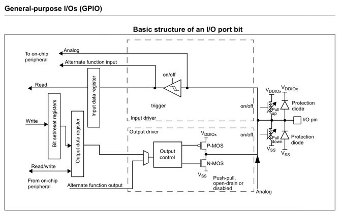
For a complex microcontroller of today, each pin could potentially hold multiple functionalities depending on how you configure them in your firmware. Shown below is a simplified illustration of how one pin on your microcontroller is like.
The IO pin would normally start off as an input only pin upon power cycling. In Arduino, we can use the following function call to initialize the pin as a input or output.
pinMode(PIN, PinDirection);
The most basic would be as INPUT and OUTPUT. Configuring a pin as:
INPUT is similar to putting them as a high-impedance state. In this mode, Input pins make extremely small demands on the circuit as they are sampling, equivalent to a series resistor in the megaOhm in front of the pin.
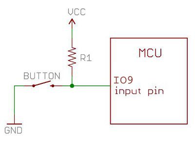
Pull-up resistors are often useful to steer an input pin to a known state if no input is present. This can be done by adding a pull-up resistor, or a pull-down resistor (resistor to ground) on the input. Some microcontroller pin have internal pull-up resistor build in, and this feature could be activated through setting the pinMode() as INPUT_PULLUP.
Pins configured as OUTPUT with pinMode() are said to be in a low-impedance state. This means that they can provide a substantial amount (Not a whole lot) of current to other circuits.
Read & Write:
We have seen the capability of the C3 CoreModule in driving it's onboard LED through the Arduino function.
digitalWrite(PIN, STATE);
I am sure you are curious about how to sample input from the physical world. Arduino has provided an easy-to-use function just to do that.
digitalRead(PIN);
Input-Output Example:
We will (for the last time) use the onboard LED and Switch the demonstrate the simple Input & Output in the Arduino ecosystem.
The button found on the CoreModule has a weak physical pull-up resistor & it is connected to IO9 pin on the ESP32-C3 microcontroller.

Todo: