Setting up our Programming environment - Arduino IDE
When you ever hear people say they used an Arduino for their project, they’re probably talking about the Arduino Uno. In this workshop, interfacing the TomatoCube* C3 RISC-V Core Module to Arduino IDE provides us with the same simple and easy-to-use UI’s loved by the Maker community. Furthermore, if you have used Arduino with a UNO before, you will find lots of the coding syntaxes remain the same.
This chapter focuses on configuring Arduino IDE to recognize & support our C3 RISC-V Core Module with Arduino IDE. Please do follow the steps carefully.
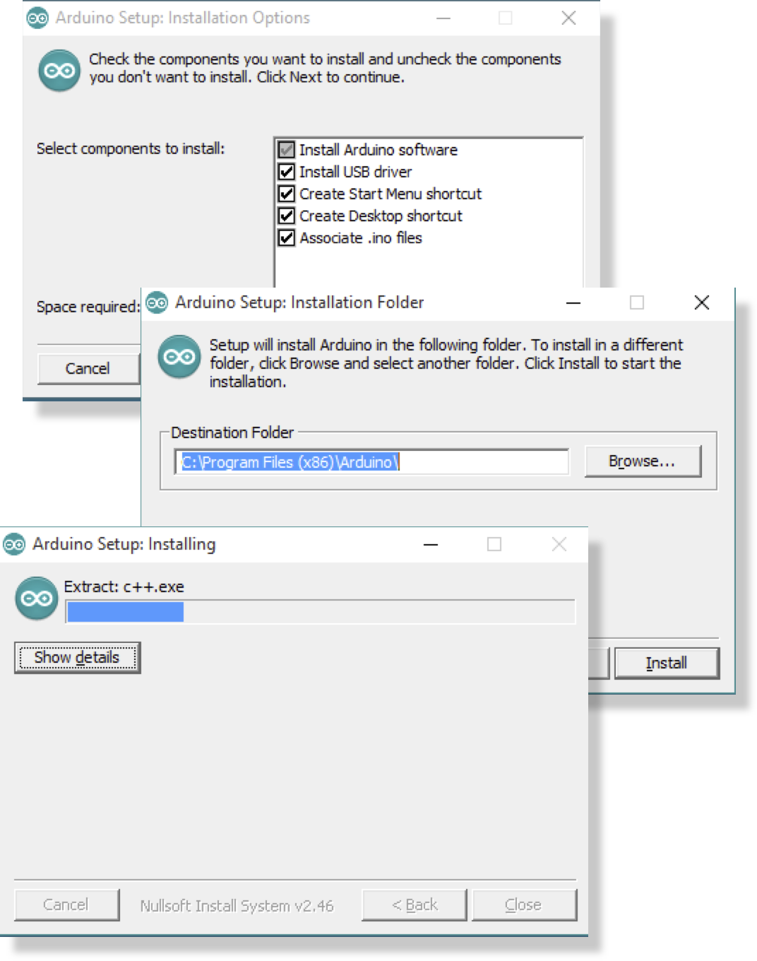
STEP 1: Installing & Launching Arduino® IDE
Follow the official installation guide found on the Arduino® website.
https://www.arduino.cc/en/guide/windows
https://www.arduino.cc/en/Guide/macOS
STEP 2: Installing the required Windows Driver
Windows only
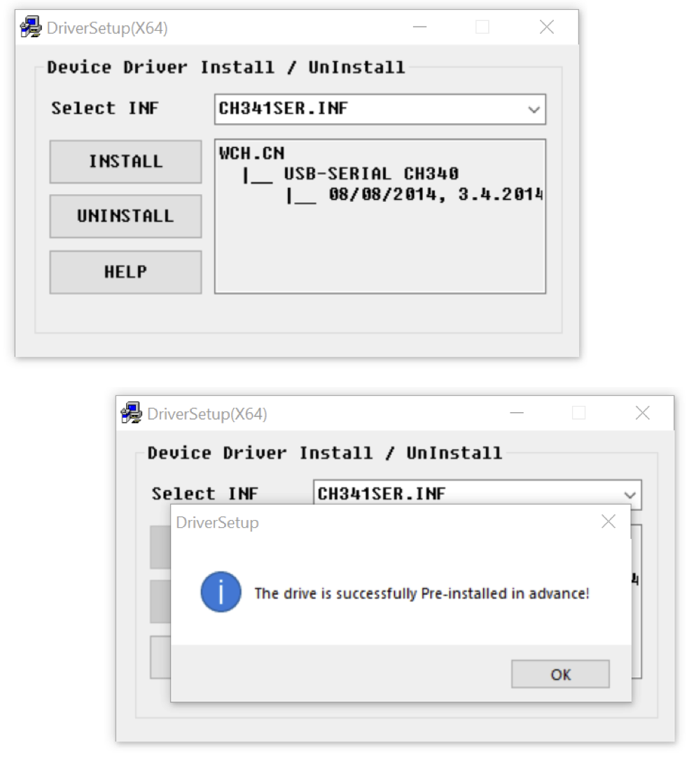
Before you plug in the CoreModule to you Laptop or PC, it is recommended to get the Driver pre-installed. 
Download the latest Windows driver from the USB interface chip's manufacturer website.
http://www.wch.cn/downloads/CH341SER_ZIP.html
Once the driver installation is completed, plug the CoreModule into any Available USB port on your PC/Laptop using a micro-USB cable.
After a series of Chimes coming from your PC/Laptop speakers, signifying a new piece of hardware is detected. Open your Windows “Device Manager” and check for the new entry under the “Ports” sub-menu.
Do take note of the enumerated Port name. “COM5” for our case.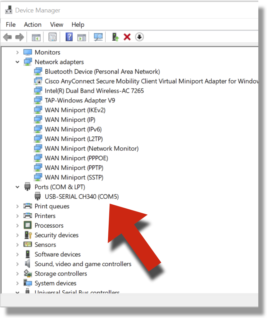
STEP 3: Adding additional board support URL
A fresh installation of the Arduino® IDE software will not be compatible with the CoreModule Hardware. Luckily for us, Espressif has been pretty diligent in maintaining a healthy Arduino® IDE add-ons. All the files can be found in Espressif's Github repository.
https://github.com/espressif/arduino-esp32
We are going to choose an easier method & rely on preconfigured script to update our Arduino® IDE & the new files in the correct locations.
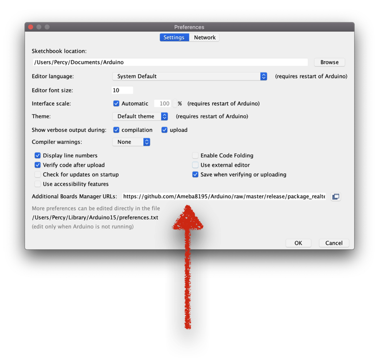
- In your Arduino IDE window, under the File menu, select Preferences.
- Choose the Settings tab.
- Add an entry into the Additional Boards Manager URLs.
- https://raw.githubusercontent.com/espressif/arduino-esp32/gh-pages/package_esp32_dev_index.json
STEP 4: Adding additional board support through Arduino Board Manager
Pop over to the board menu to bring up Arduino's Board manager tool window.
- In your Arduino IDE window, under the Tools menu
- Choose the Board:... menu.
- Select Board Manager once the submenu popped up.
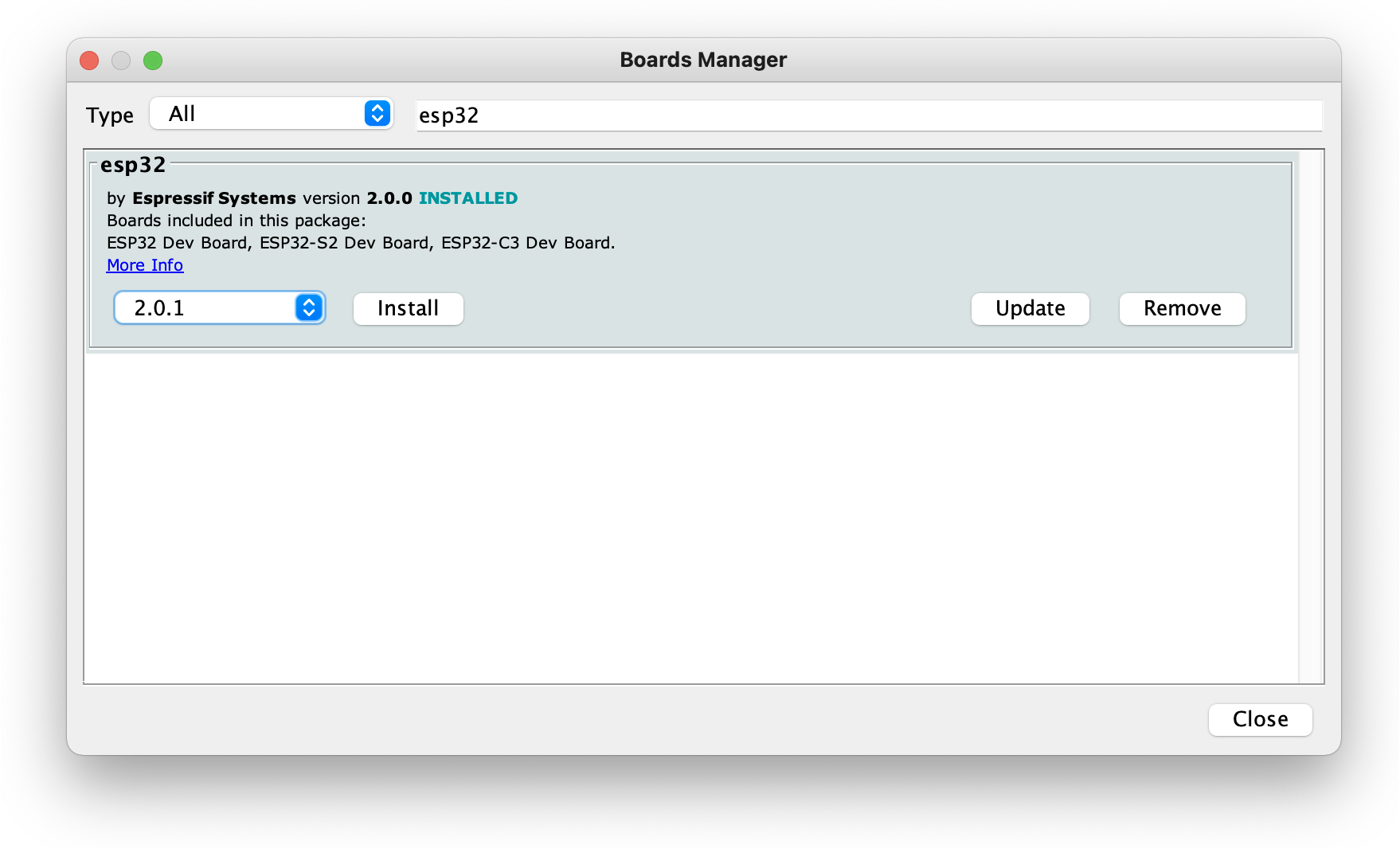
In the Boards Manager, search esp32 by Espressif Systems. Install the latest version (version 2.0.1 as of this writing).
STEP 5: Choosing the right board
It is going to take a couple of minutes (Dependent on your internet speed) Once completed, we will need to instruct Arduino to generate the code (Compile the code) for our RISC-V CPU architecture based ESP32C3 Core module.
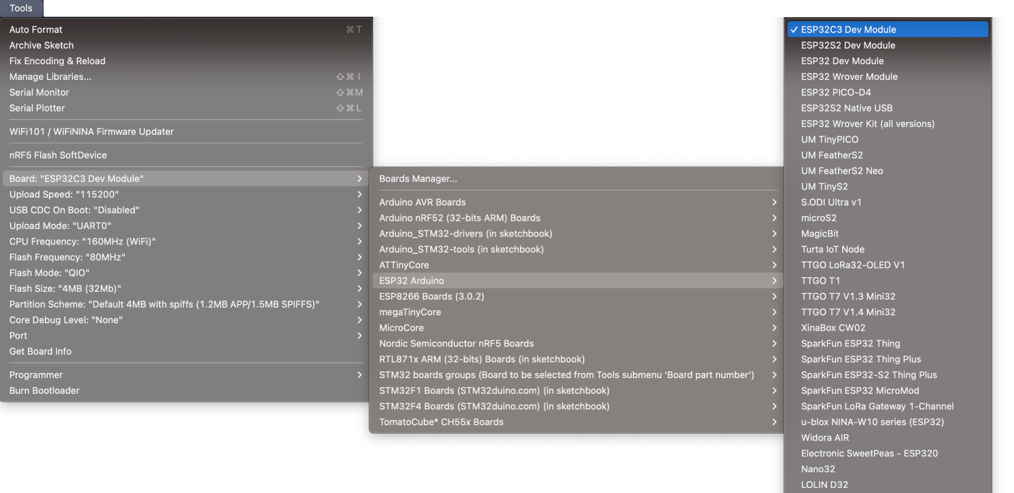
- In your Arduino IDE window, under the Tools menu
- Choose the Board:... menu.
- Mouse over the entry ESP32 Arduino.
- Pick the very first board entry in the popup submenu ESP32C3 Dev Module.