Basic Programing Construct (ii): Conditional
Conditionals are found in all forms of programming.
They allow our program to react to conditions and make a choice from one or many choices.
In Arduino, there are 3 types of conditional construct at our disposal. Each of them would have a conditional to be fulfilled, followed by a statement or block of statements to be executed.
A) If & nested If construct
If takes an expression in parenthesis and a statement or block of statements. If the expression is true then the statement or block of statements gets executed otherwise these statements are skipped.
if (condition) {}
else if (another condition) {}
else {}
In the event where there are multiple branches of decision that needs to be made. One or more else if statements are presented.
Lastly, we will have an optional else statement, which executes when all the conditional/expression are false.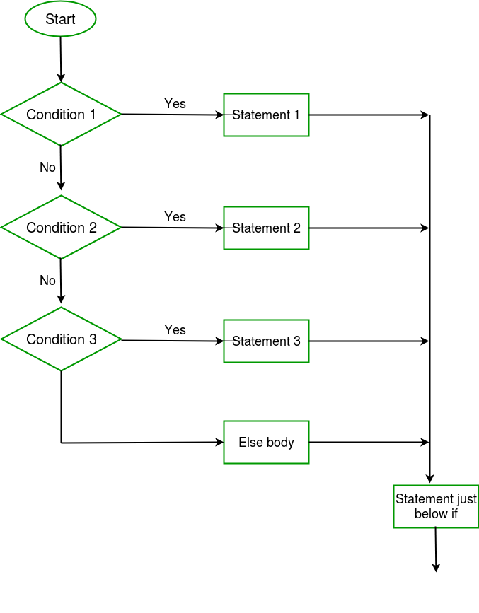
B) switch case statement
Like the if statements, switch...case controls the flow of programs by allowing the programmers to specify different codes that should be executed in various conditions.
switch (variable) {
case label:
// Statement
break;
default:
// Statement
break;
}
The break keyword makes the switch statement exit, and is typically used at the end of each case. Without a break statement, the switch statement will continue executing the following expressions ("falling-through") until a break, or the end of the switch statement is reached.
C) ?: Conditional operator/ternary operator
expression1 ? expression2 : expression3
Expression1 is evaluated first. If its value is true, then expression2 is evaluated and expression3 is ignored. If expression1 is evaluated as false, then expression3 evaluates and expression2 is ignored.
The result will be a value of either expression2 or expression3 depending upon which of them evaluates as True.

Conditional require Comparison:
When discussing Comparison in the computer software world, the questions that computers ask only have two possible answers: Is it True or False.
True or False is known as Boolean (recall Boolean type variable?)
There are many operators (symbols) that we could use to aid our computer in making those decisions.
Conditional Operators:
| Operator Symbol | Name | Description |
|---|---|---|
| == | Equal | Checks if the value of two operands is equal. |
| != | Not Equal | Checks if the value of two operands is not equal. |
| < | Less Than | Checks if the value of left operand is less than the value of right operand. |
| > | Greater Than |
Checks if the value of left operand is greater than the value of right operand. |
| <= | Less Than or Equal to |
Checks if the value of left operand is less than or equal to the value of right operand. |
| >= | Greater Than or Equal to |
Checks if the value of left operand is greater than or equal to the value of right operand. |
Multiple comparison
In Arduino you can also combine multiple comparison by using the Boolean logical operators.
| Operator Symbol | Name | Description |
|---|---|---|
| && | and | Called Logical AND operator. If both the operands are non-zero then then condition becomes true. |
| || | or | Called Logical OR Operator. If any of the two operands is non-zero then then condition becomes true. |
| ! | Not Operator | Called Logical NOT Operator. Use to reverses the logical state of its operand. If a condition is true then Logical NOT operator will make false. |