i2c Bus protocol:
An inter-integrated circuit (I2C) is a system for serial data exchange between the microcontrollers and specialized i2C compliant integrated circuits (IC).
It is used when the distance between them is short. Connection is established via two conductors. One is for data transfer(SDA), and the other is for synchronization (SCL) (clock signal).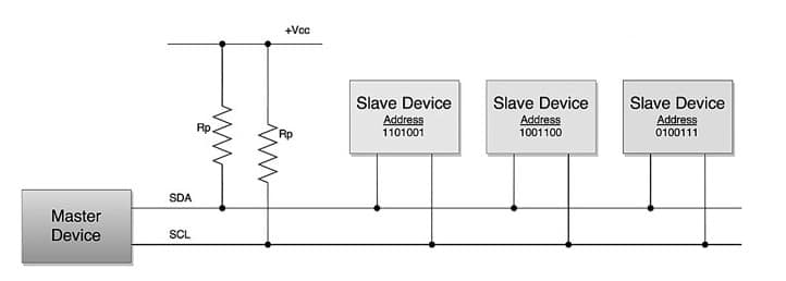
As seen above, one device is designated as the bus master. It addresses one slave chip (with a unique address) before the communication starts.
In such a way, one microcontroller can potentially communicate with 127 different devices.
wiki: https://en.wikipedia.org/wiki/I²C
Throughout the workshop, the ESP32-C3 microcontroller will act as the i2c Master transmitter; the co-processor and the sensor peripherals will take the role of slave receivers.
Arduino function used by the i2c Master transmitter:
Wire.begin(SDA_Pin, SCL_Pin);
The above function call Initialize the i2c as a bus master.
When we are going to write data to a particular slave device on the bus, we need to initiate the communication with it's address. In Arduino, we use the 7-bit addressing convention instead of the 8-bit address.
Wire.beginTransmission(SlaveAddress);
Wire.write(value);
Wire.endTransmission();
To read data as an i2c Master, the Master needs to request and then read bytes of data that are sent from the uniquely addressed Slave device.
Wire.requestFrom(SlaveAddress, BytesNeeded);
while(Wire.available()) {
Wire.read();
}
Bare-metal i2c peripheral communication:
To kickstart our i2c journey, we will pick one of the most simplest i2c integrated circuits (IC) I could find on the market.
PCF8574, A 8 bits port expander by Texas Instruments (https://www.ti.com/lit/ds/symlink/pcf8574.pdf). This is a useful component when the embedded design calls for lots of IO pins to either drive peripherals or sample reading from sensors.
To use the i2c device, the first thing you will need is the i2c slave device address. Looking at the schematic below, we can see the hardware address pins being configured as such: (With VCC as 1 and GND as 0)
- A2 => 0
- A1 => 1
- A0 => 1 (PullUp Default) / 0 (Jumper short if required).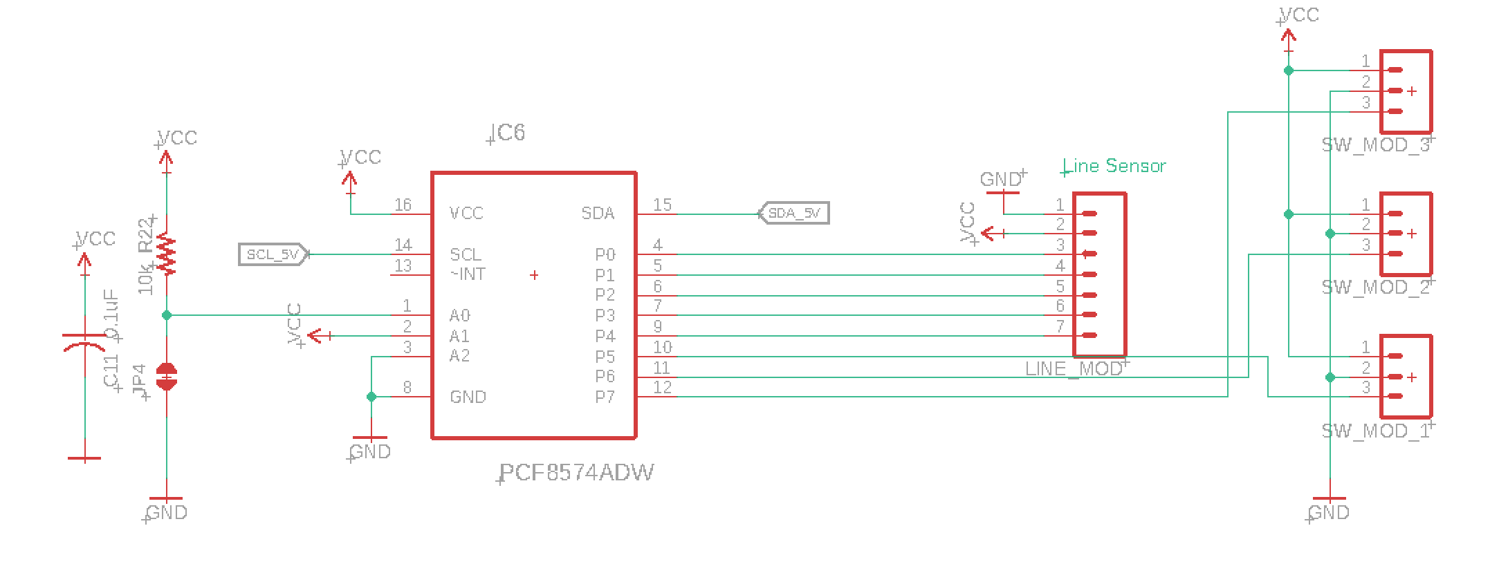
It is quite common for ICs to come with hardware address setup pins. This would allow multiple same ICs to be used on the same i2c Bus.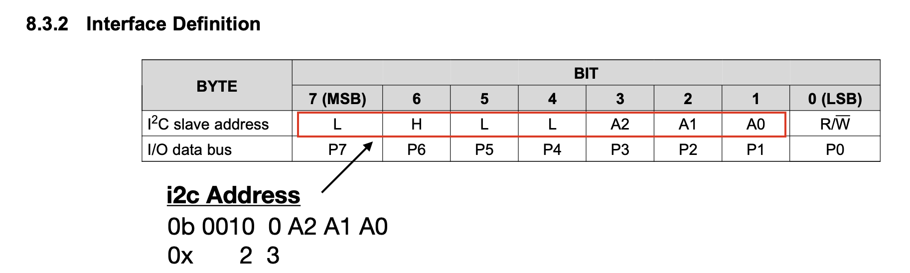
Referring to the datasheet, we can conclude the i2c address as 0x23 (default) / 0x22 (Jumper shorted).
To learn more about Number system

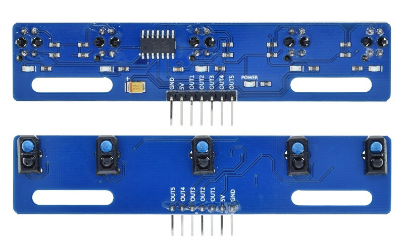
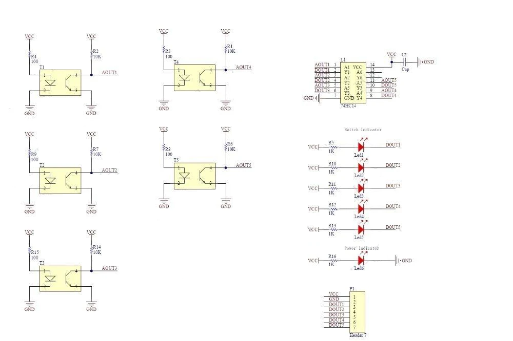
Endstop switch (micro-switch) module:
The mechanical endstop switch module uses a lever switch to detect when it is activated (pressed). The switch is wired up so that when activated, it pulls the signal the signal wire (Green) LOW.
You will notice there is a capacitor onboard which is placed in the module to debounce the switch's input.
There is also an LED on the board that will light up when the switch is activated.
What is Debouncing?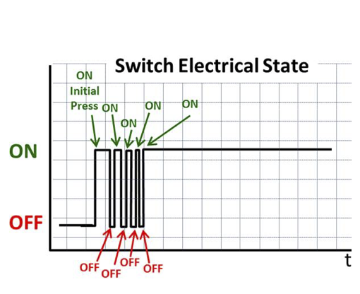
Debouncing - When you activate a trigger(e.g. switch) there is a period where the electrical contacts within the switch may bounce before settling.
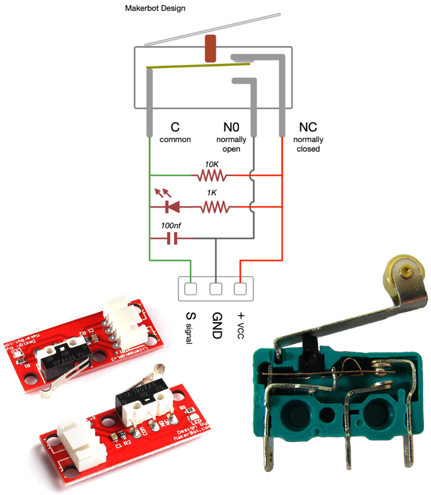
Check that the wires are hooked in correctly powering up the board.
Green -> Signal
Black -> Ground (GND)
Red -> VCC